|
|
adres do korespondencji: |
adres
firmy: |
|
tel. +48 58 671-74-07 fax. +48 58 679-56-56 tel. +48 601-68-78-53 e-mail: atmor@atmor.pl |
||
![]()
| |||||
|
|
|
IMPULSE MEASUREMENT OF LIGHTNING PROTECTION EARTHING IMPEDANCES
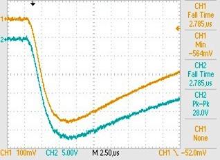
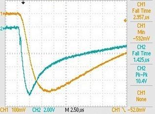
1. INTRODUCTION Needless to say, earthing systems for lightning protection should be characterized by a small voltage drop across them when the lightning current is carried away to the ground. Voltages in the form of disturbances in the power supply system can be dangerous for people as well as for the system and computer devices. Because of considerable lightning current rise (to 100 kA/ms), the effectiveness of earthing systems is often determined by inductive voltage drops. For a wider earthing arrangement, one should also take under consideration the wave phenomenon in conductors[1,2]. National standards recommend a maximum value for earth resistance (10 W is a value found in many standards as for example in British Standard BS 6651 [3] or the European one [4]) to insure that the maximum value is not exceeded and they add engineering rules to try to limit the impedance. So in general the problem of line tower earthing measurements must be solved. The impulse method of line tower earthing tests was put forward at Padova University [5] and later developed as well as brought into measurement practice at Technical University of Gdańsk [6,7,8,9]. With regard to speed of analysed courses as well as shift in time between an impulse current and voltage drop caused by it on the tested earthing, technical realization of measurement is not an obvious thing. There can be applied different definitions of impulse resistance, as well as of operating temporary values, but only the definition using peak values of current and voltage drop has found practical realization. Such a way corresponds to the European Standard [2], where a definition of an "earthing equivalent resistance" is explained as "a ratio of maximum values of voltage drop and current, whitch usually are not at the same time". In Fig. 1a and 1b typical shapes of an impulse current and a voltage drop accros an earthing can be seen [8]. An oscillogram 3a refers to a concentrated earthing and 3b to a wide one. The obtained results of impulse impedance involved calculation of impedance in the time domain due to time shift between a current and a voltage drop according to diagrams like shown in Fig 1. The calculations have been performed by the formula (1):
a) b)
Fig. 1. Oscillograms of impulse current (channel 1) and voltage drop (channel 2) across earthing recorded for a concentrated earthng - a and for a wide one - b
The main aim of the presented work is to find measurement procedures of efficiency evaluation for lightning protection earthing systems. Especially analysis of an influence of an impulse current amplitude onto received results have been taken into consideration. The investigations have been carried out at a current rise time of 4 ms and peak values from 1 to a few hundred amperes.
2. EFFECTIVE LENGTH OF EARTHING Requirements of low resistance in impulse conditions can not be realized by extension and enlarging of buried ground wires as is broadly practised in the case of service earthing. Too wide earthing does not allow for suitable protection effectiveness at lightning currents due to wave phenomena. Consideration of the time constant of earthings and current wave velocity shows, that enlarging of earthing size is effective only to a certain value, wich is called effective length. According to Szpor, the effective length can be expressed as [10]:
where:
T – rise time of current impulse
Fig. 2 shows results of model simulations for the effective length of earthing as a function of ground resistivity for current impulses with front times of 1, 4 and 8 ms. The effective results given above have been calculated at the assumption that the resistivity of the ground surrounding the earthing is constant. One can see that the effective length of earthings is extremely low for well conductive grounds and objective investigations refer to soils of resistivity below 150 Wm.
Fig. 2. Effective length of earthing versus soil resistivity for impulse current rise time 1, 4 and 8 ms
3. IMPULSE TESTS OF TRANSMISSION TOWER EARTHINGS 3.1. General remarks The impulse method allows us to measure earthings of overhead transmission lines without disconnection of testing terminals with artificial earthing fasten to the tower construction. The length of spans of transmission lines in most of cases exceeds 150 m, and a wave impedance in the lightning conductor – ground arrangement equals about 500 W. During measurements at impulse currents, a tested earthing with impedance (or impulse resistance) of Zx is shunted by wave impedances Zwc of earth wires running to both neighbouring towers as it can be seen in Fig. 3a. In an equivalent circuit shown in Fig. 3b it has been taken into account also wave impedance of tower Zwt and earthing resistance of towers Ze [11]. Taking into consideration that scheme, a value Zm measured between terminals 1 and 2 acrosss Zx can be calculated by a formula (3):
Fig. 4 shows calculation results of relative errors of tower earthing impedance Zm with usage of the formula (3). The error was determined as (Zx - Zm)/Zx versus Zx for the following assumptions: Zwc = 500 Ω, Zwt = 100 Ω [10] and Ze = 10 Ω. One can noticed, that for usually met in practice values of Zx up to 20 Ω, relative errors due to shunting influence of neighbouring towers can be estimated on a level of 5 %. a)
b)
Fig. 3. Arrangement of tower earthing test with two neighbouring towers – a) and its equivalent scheme – b)
Fig.4. Relative error of Zm calculations versus Zx
Impulse tests of tower earthing have been performed using an impulse meter manufactured in Poland. The meter looks like a typical multimeter and generates impulse currents of about 1 A at a voltage of about 1000 V. Front times of the applied impulses are equal to 4 ms. Oscillograms presented in Fig. 1 have been recorded on real earthings using an impulse meter mentioned above and shown in Fig. 5.
Fig. 5. Impulse meter of earthing impedance manufaktured in Poland by ATMOR SC
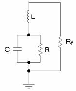
3.2. Computer simulations Theoretical calculations of accuracy of earthing impulse measurements performed in agreement to Fig. 3 and formula (3) are shown in Fig. 4. The obtained results have been verified by computer simulations. An usual line model has been applied to shape the wave impedances of lightning conductor Zwc and line tower Zwt . Parameters per length unit in the model have been calculated as resistance R, inductance L, capacity C and conductance G. The length of the modelled lightning conductor has been changed up to 300 m like transmission line spans are changed. A tower earthing Ze usually consists of both a tower foundation and an artificial earthing. It is in common practice, that the artificial earthing is realized as a mesh type one. For computer simulation purposes the tower earthing was arranged as a parallel connection of the artificial earthing denoted by simplified model with parameters R, L, C and the tower foundation denoted by a resistance Rf as it was arranged in Fig. 6.
Fig. 6. Parallel connection of artficial earthing (R,L,C) of line tower and its foundation (Rf)
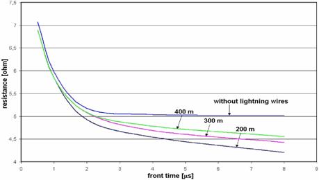
Computer simulations were carried out using MATLAB – SIMULINK software package. Currents and voltage drops across the earthing model were recorded in a circuit of a current impulse generator. Parameters of the modelled generator were similar to those of the impulse meter mentioned above. Fig.7 shows an influence of impulse front time on impulse resistance of tower earthings. A curve described as “without lightning wires” refers to a situation when lightning wires are disconnected from a tested tower on its top. The residual curves concern shunting the tested tower earthing by two neighbouring tower eartings with expressed span lengths. Fig. 8a depicts an influence of line span length on an diferrence between a measured value of a tower earthing resistance Zm and its realy value Zx at impulses of 1 μs front time. In Fig. 8b one can see similar relations obtained for 4 ms front time. The differences have been illustrated in Fig. 9 as a relative error ((Zx - Zm)/Zx ) and expressed in %. One can notice that for the 300 m span length an error due to neighbouring tower shunting decreases to about 3 % at the impulse of 1 μs. When 4 μs impulses are applied for simultions the obtained errors seem to be a bit higher and for 300 m span achieve a value of about 10 %. Taking into account an general accuracy of earthing measurement method such evaluated error can be provided with acceptance.
Fig. 7. An influence of impulse front time on impulse resistance of tower earthings without shunting of neighbouring tower and with parallel connection of different length of spans
a) b)
Fig. 8. Influence of span length on test error due to neighbouring tower shunting at impulse front time of 1 μs (a) and 4 ms (b)
Fig. 9. Influence of span length on test error due to neighbouring tower shunting at impulse front time of 1 and 4 μs
3.3. Real test results In Fig. 3 one can notice, that during resistance tests of tower earthings at opened testing terminals, quite different measurement objects are taken into consideration than that under normal service conditions. Lightning currents are carried away to the earth both through artificial earthing and through tower foundations. Further investigations of tower earthing methods were performed on a transmission line as real tests and as computer symulations. During the tests, lightning protection conductors could be isolated from a tested tower at its top. Impulse resistance results of computer simulations and such real tests have been shown as histogram in Fig. 10, where: 1. Zc denotes the resistance with both artificial earthing and lightning protection conductors are connected to the tower, so shunting influence of neighbouring tower earthings is observed, 2. Zi – artificial earthing connected with the tower, but the lightning conductor isolated from the tower on its top, so there is no shunting 3. Za – artificial earthing conductor disconnected from the tower (testing terminals are open) - artificial earthing is measured only, 4. Zf - the lightning conductor isolated from the tower on its top and testing terminals are open, so a foundation resistance is measured only
The difference between Zi and Zc can illustrate the real influence of neighbouring tower earthings on measurement results. In the presented example such percentage differences are equal to 6 % for real tests and 11 % for computer simulations, what coincides with calculations and simulations mentioned above.
Fig. 10. Real test and computer simulation results of tower earthing resistance performed at 4 μs impulses, where Zc states the resultant resistance as parallel connection of artificial earthing and foundation with shunting influence of neighbouring towers, Zi – parallel connection of artificial earthing and foundation without shunting influence of neighbouring towers, Za – artificial earthing resistance, Zf - foundation resistance
It is common practice in tower earthing measurements of overhead transmission lines equipped with lightning protection conductors, that the results obtained using a low frequency method with disconnected testing terminals of earthing are taken as reliable. Such a way seems to be not only expensive and time consuming, because the testing terminals have to be unbolted and the line switched off. However, the measurement procedure does not take the tower foundations into consideration. The results in Fig. 10 point that the impulse resistance of a tower foundation can be comparable with that of the artificial earthing. Isolating of lightning conductors at the top of towers during static tests is the only way to take into account the participation of tower foundations in carrying away of lightning current to earth. The impulse measurement method of tower earthing resistance allows us to eliminate the inconveniences and to take into consideration a parallel connections of tower foundations and artificial earthings.
4. LIGHTNING EARTHING MEASUREMENTS OF BUILDING
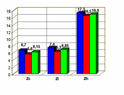
The usefulness of the impulse method for lightning conductor evaluation was tested on an example of a 1-staircase building of 8 storeys. Lightning protection system of the building has 6 vertical conductors connected to a rectangular type earthing. Each of the vertical conductors is equipped with a testing terminal. Results of impulse resistance measurements performed for each vertical conductor are presented in Fig. 11, were: Zc – the testing terminal connected, Zl – the terminal disconnected and the meter connected to the tested conductor below the terminal, Zh – the terminal disconnected and the meter connected to the tested conductor above the terminal. In Fig. 11 one can see that impulse resistance results obtained at the connected terminals (histogram marked as Zc ) are about 10 % higher than these of the disconnected terminals (Zl ). Results described as Zh refer to a situation in which a tested vertical conductor is disconnected from the buried wire of earthing, for example, it may have been broken below the earth surface. An analysis of measurement results obtained without disconnection of conductors allows for fast evaluation of the tested protection system. When the resistance of any conductor is much higher (in the case of the analysed building about twice) than the others, it can prove a lack of metallic connection between the conductor and the buried earthing wire.
Fig. 11. Maximum, minimum as well as average of six values of impulse resistance of lightning protection system of building obtained for each vertical conductor; Zc – testing terminal connected, Zl – terminal disconnected and meter connected to tested conductor below terminal, Zh – terminal disconnected and meter connected to tested conductor above terminal
5. CONCLUSIONS The presented methodology of earthing resistance measurements using impulse currents permits to consider inductive drops caused by these currents, and so it makes possible the best evaluation of earthing systems for lightning protection purposes. Resistance tests of line tower earthings by means of clasic low frequency meters need disconnection of the tested earthing from the tower, so it is time consuming and the line must be switched off. Because a lightning current is carried away to earth through both the earthing of a line tower and through its foundation, earthing resistance testing should be performed with parallel connections of these elements. Use of impulse current makes such tests possible and, what is more, they can be done on line in service It has been stated, that the influence of neighbouring tower earthing reduces obtained results. The reduction depends on the impulse front time as well as on the line span length and for analized conditions this has been evaluated within the range of 3 to about 10 %. The presented impulse method permits evaluation of lightning protection installations of different objects for example buildings without disconnections of testing terminals of the installation
6. REFFERENCES
1. Lorenzou M. I., Hatziargyriou N. D. „Effective dimensioning of extended grounding systems for lightning protection”, Proceedings of 25-th LCLP, Rhodes, Greece, 18-22 Sept. 2000 2. Mazzetti C., Veca G. M., “Impulse behaviour of ground electrodes”, IEEE Transaction on Power Apparatus and Systems, vol. PAS-102, No. 9, 1983 3. “Protection of structures against lightning”, BS 6651, 1999 4. “Protection of structures against lightning, part 1, General principles”, ENV 61024-1, 1995 5. Galeazzi A., Marenesi R., Paolucci A. „Ohmmetre de terre en ondes de choc pour la determination des resistances de terre dans les lignes de transmission avec fil de garde”, Rapport CIGRE No. 329, 1954. 6. Szpor S., Kosztaluk R., Ossowicki J., Suchocki J., ”Mesure de la resistance de terre pylone de ligne de transmission en ondes de choc repetees”, Bull. SEV 62(1971)21, 16. Oktober 7. Galewski M., Wojtas S., Wołoszyk M., „Impulse earthing measurement”, IMEKO XIV International Congress, Tampere (Finlandia) 1997 8. Wojtas S. “Efficiency evaluation methods of earthing systems for lightning protection purposes”, Proceedings of 26-th ICLP, Krakow, Poland, 2-6 Sept. 2002 9. Wojtas S., Galewski M., Wołoszyk M., " Impulse measurements of tower earthings of overhead transmition lines, Proceedings of 16-th EMD, Kaunas, 2006 10. Szpor S., "Lightning protection", Copyright by Wydawnictwo Naukowo - Techniczne, Warszawa 1973-78 (pol.) 11. Wojtas S. " Impulse measurement accuracy of transmission line earthings", Proceedings of 29-th ICLP, Uppsala, Sweden, 2008
USER MANUAL
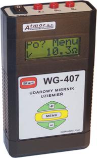
EARTHING IMPULSE METER Type WG-407
1. Description of the meter 1.1. General remarks A meter WG-407 has been designed for earthing resistance measurements at impulse time parameters similar to those met at real atmospheric discharges. The applied impulses achieve a value of about 1 A at a voltage of about 1000 V. Time parameters of the measurement impulses fulfil requirements of the following standards: PN-92/E-04060 and PN-EN 60060-2:2000. The meter has been designed for checking of all lightning protection earthings, especially in objects submitted to increased rigours and specially protections required by PN-89/E-05003/3 and PN-89/E-05003/4, for example petrol or gas stations. The meter is eapecialy useful for measurements of transmission line tower earthings. Resistance tests of line tower earthings by means of clasic low frequency meters need disconnection of the tested earthing from the tower, so it is time consuming and the line must be switched off. Use of impulse current makes tower earthing tests without disconnections and, what is more, they can be done on line in service. There can be applied different definitions of impulse resistance, as well as of operating temporary values, but only the definition using peak values of current and voltage drop has found practical realization. Such a way corresponds to the European Standard PN-IEC 61024-1, where a definition of an "earthing equivalent resistance" is explained as "a ratio of maximum values of voltage drop and current, whitch usually are not at the same time". 1.2. Technical data
· 2 stakes (f 10 mm, 0.6 m long) · single conductors 1x0.75 mm2:
· net power supply
1.3. Description of the meter
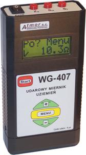
Fig. 1. Meter WG-407 - a general view
The meter can bee seen in Fig. 1, where: 1 - switch "Zasil" - the meter is turn on and off, on a LCD display appears an inscription: ATMOR WG407 and a few seconds later "Menu measure" 2 - “Zx” – a socked to be connected with the tested earthing 3 - “Su” – a socked to be connected with the voltage probe 4 - “Si” – a socked to be connected with the current probe 5 - LCD – a liquid crystal display, the display may be light up by pushing a button "+" 6 - a button "Start" - when you push that button a measurement or another process chosen by the button "Menu" is started, 7 - a button "Menu" - a choice of operation mode of the meter: a) measurement b) memory service: writing, reading or erasing measurement results c) battery test 8 - a button "+" - an increase of a number of a read memory cell or light up the display after measurement 9 - a button "-" - a decrease of a number of a read memory cell 10 - a battery charging socked
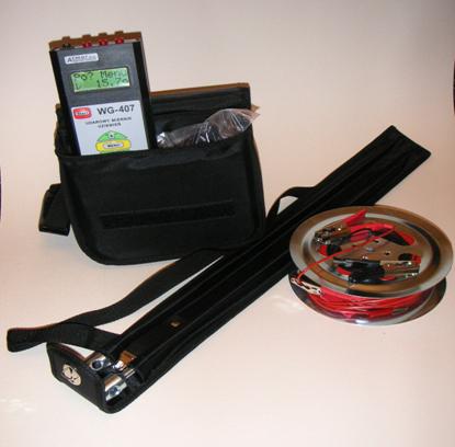
1.4. Meter accessories The WG-407 meter with its accessorie has been shown in Fig. 2
Fig. 2. General view of the meter and its accessories: 1- the meter WG-407, 2 –bag, 3 – reel with conductors, 4 – net power supply for battery charging, 5 –protective coverof measurement probes
2. Measurements 2.1. Safety of service It is not allowed to connect the meter measurement sockeds to any voltage source. The WG 407 meter has not designed for short circuit loop resistance measurements! During the meter operation industrial safety rules should be applied. The meter is supplied from a battery of 4.8 V and it generates impulse currents of about 1 A at a voltage of about 1000 V. Front times of the applied impulses are equal to 4 ms. Pulse rate of the meter is equal to about 5 per second. If somebody touch an output socked of the meter an current amplitude is decreased by human body resistance (about 3 kW). Current impulses of such amplitude and such short duration are not dangerous for peoples, but they can be very unpleasent for somebody touching a measurement circuit. It is not allowed to use: · a humid or damaged meter · measurement conductors with out of order insulation
2.2. Conditions of correct measurements In order to obtain correct measurement results the following coditions has to be performed: · Resistance of both current and potential probes should be less than 1000 W. In opposite situation when you push the button "Start" an inscription "ERROR! VOLTAGE" or "ERROR! CURRENT"is shown. A test can be carried out if probe resistance is reduced, for example biger stakes or a few stakes connected in parallel. · In order to reduce an influence of electromagnetic coupling on obtain measurement results probe coductors should be placed at a distance of more than 5 m between them. This condition may be easy meet when the probes are arranged in a configuration shown in Fig. 3
Fig. 3. A suggested configuration of measurement probes
2.3 Measuring, writing, reading and erasing procedures 2.3.1 Measuring · Drive probes into soil, reel off conductors and connect them to the meter taking into consideration remarks mentioned in p. 2.2, · Power on the meter using swich “Zasil”, wait until the display shows the inscription "ATMOR WG 407" and a few seconds later the inscription “Menu measure”, the meter is ready to measurement, · Push the button “Start”, the meter perform a mesurement circuit test (the inscription "testing circuit") and the display shows a result of a tested earthing - an inscription: "me? Menu ...W". In this state yuo can light up the display pushing the button "+". Every following pushing the button “Start” starts a mesurement procedure. If you see the inscriptiont "ERROR! VOLTAGE" or "ERROR! CURRENT" instead of an measurement result, measurement circuit resistance seems to be to high - see p. 2.2.
2.3.2 Writing, reading and erasing procedure in memory · In order to write a measurement result shown on display you should push the button “Menu” , the inscription “write Me ... W” appears and when you push the buttonu “Start”, a result from the display is writen in the meter memory and an inscription "OK ... Me ...W” appears on the display. A number in the first part of the inscription shows a position of the writing in the meter memory. A result is writen at the lowest free position. When you push the button “Start” at the inscription "OK ... Me ...W”, a measurement procedure is started again without change of operation mode by usage of the button “Menu”. · In order to read writen in the memory results you should push the button “Menu” until an inscription “Menu read” appears and then push the button “Start”. An inscription “## ... Me ...W” on the display appears, where the first number denotes a position of a result shown on a second position. You can change the read position by pushing the buttons "+" or "-". · A storage capacity is able to read 126 results. In order to erase and clear the meter memory you should find an inscription “write Me” or “write Me ...W”, next push and keep the button “+”, then push and keep the button “-“, afterwards you should release the pushed button “+”, and the button “-“ must be kept until you see an inscrition “clear Me”, afterwards release the pushed button “-“. If you push the button “Start” at the inscrition “clear Me” all results writen in the meter memory are erased.
3. Supply system of the meter 3.1 Battery test The meter WG-307 is powered by a 4.8 V Cd-Ni battery. A battery set of capacity 700 - 1000 mAh as usualy the meter is equipped seems to be sufficient to perform about 1500 measurements. A battery container there is under a cover on a rear panet of the meter. You can remove the cover pushing the cover in a direction shown by an arrow with inscripion „OPEN”. In order to check a battery charging ratio you should push the button „Menu” until an inscription „Bat. Menu Test” appears and then push the button „Start”. The meter starts to test the battery (an inscription „Test bat. >>>”) and finaly an inscription „Test bat. ...%” appears. The number denotes a level of battery charge. When a battery voltage becomes to low, the meter resets and on its display appears an inscriptiona "ATMOR WG 407".
3.2 Battery charging The meter is equipped with inner charging system and the battery can be charged without taking out the battery from a container. In order to start with battery charging procedure you should swich off the meter and a net power supply pin must be plug to the meter socked. The meter starts with a charging procedure automaticaly. At the begining the charging level of the battery is checked and on the display appears an inscription „Charger test bat”. If the battery level is higher than 30% of rated one, an inscription „Charger Ful” and the battery is not charged. In opposite situation a two stages charging process starts. First stage refers to battery discharging - an inscrition „ Charger discharg”. In the second stage appears an inscription „Charger charging” and the meter starts to charge battery. When you noticed an inscription „ Charger Full” it denotes that the charging process has been finished.
4. Maintenance Electrical circuit of the meter does not require maintenance. Accuracy check of the meter should be done accordingly to Producer’s Standard WT-06-01/407. The meter is powered with NiCd accu pack of 4.8V. In emergency 4 AA alkali batteries can be used. Battery compartment is on the back of the meter. The confirmation of the accuracy is made in Okregowy Urząd Miar in Gdańsk (PL).
5. Warranty The producer gives 1-year warranty. The warranty card is on the last page of the manual user. ATMOR sc Elektronika Pomiarowa ul. Chałubińskiego 29 80-809 Gdańsk office adress.: ul. Kujawska 4/9, 84-232 Rumia tel., fax (0-58) 679-56-56, 0-601-68-78-53
Warranty of EARTHING IMPULSE METER
Type WG-407, Nr _____________________ Gdańsk, date________________________________________
DOWNLOAD
|
|
|